|
Combining Textures and
Pictures with Specialized Texture Synthesis
by Alex
Eilhauer, Alice Pritikin
and Dylan Weed
(under the direction of Steven J. Gortler)
|
|
|
|
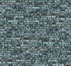
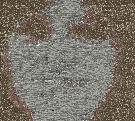
| Stone wall |
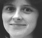
Woman |
Woman in stone wall:
The brick texture has been rearranged / recreated
so that an image of the woman's head appears in the
bricks. |
|
Abstract
This project attempts to combine an image and a texture (or two
textures) to create a result that looks like the image, but is
made out of the material in the texture. This is different from
overlaying the texture on the image. Rather than simply combining
the colors, the program builds the image out of components from
the texture. In doing this, it attempts to preserve both the local
continuity of the texture and the overall shading/continuity of
the generator image. This is accomplished by using a markov random
field sampling algorithm combined with tree-structured vector
quantization to quickly find new pixels that match both the texture
and the image.
|
1.0 Our Goal and Introduction
Traditionally, one can combine textures and images simply by placing
one on top of the other (while making it partially transparent).
This method simply imposes the shading of the picture onto the
texture instead of fundamentally recreating the texture to look
like the image. Furthermore, it can create colors that were absent
in the original image (thus destroying the texture). For instance,
if I decide to create a picture of a rose out of wood, then combining
transparent layers will generate a piece of wood which appears
to have a pink rose painted on it lightly. Anyone glancing at
the picture will immediately realize that wood is not pink or
green. Instead, with this project, we are aiming to create a piece
of natural looking wood in which the grains of the wood appear
to outline a "rose shape" on their own. With this method,
we preserve the color and texture of the wood and simply alter
it to mimic the rose shape. Hopefully, the casual observer will
think this piece of wood naturally grew into a shape with the
rose-like features.
The paper is organized as follows: In the first section, we will be presenting our
goals more rigorously. In section 2 we outline the algorithm. Section 3 presents our
results, and finally section 4 outlines some areas for future progress.
|
1.1 An Example Texture-Image Combination:
Here we will demonstrate the difference between actually combining
a texture with an image and simply overlaying the two images in Photoshop.
For this demonstration, we will be using a picture of folded silk
and the same woman as above. Note, to make the examples clearer, I
have zoomed in on her eyes in each picture, because that is the region
of highest contrast. |

|
Silk - This is the full picture of silk we
used in the algorithms below. Because the images are
blown up, you will only see a small section of silk.
|
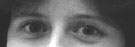 |
Woman's eyes (Close up) Note the sharp contrasts
between light and dark.
|
1.2 The Wrong Way:
Here, we have simply overlayed an image of silk on top of
an image of a woman. Note that the face does not appear to be
made out of silk. Instead, it looks as if she is peering
through a silk veil. Furthermore, this depiction includes
colors never seen in the original silk cloth. The whites are
whiter than the highlights in the silk, and overall it has a
lighter color. |

|
Combination of silk and woman using Photoshop
(close up) The silk and woman images were combined by making
one partially transparent and overlaying the other in Adobe Photoshop.
|
1.3 The Right Way:
Now, instead of just overlapping the two images, we will attempt to
create the woman's eyes by picking out pieces of the silk texture
that match the shading of the woman's face in a given region.
1.3.1 Not Enough Emphasis on Texture:
The simplest way to accomplish this task is to look at
each point for the pixel in the silk image that most
closely resembles a given point on the face. This
simple method solves one of the problems encountered
above - the colors are now accurate. The extreemely
light blue color no longer appears on her nose and
eyes. On the other hand, by restricting ourselves to
the colors in the silk image, we limit our palette. As
evidenced below, the silk image does not contain a
lighter blue to emphasize the nose and thus the nose
blends in to the rest of the face.
But, even though the colors match those in the silk, the picture
does not look like silk. When picking a pixel from the silk image
for each point, we looked only at the woman's picture and ignored
the surrounding silk pixels. Thus, we have an image in the right
color palette but without the feel of cloth.
|

|
Application of silk colors to create woman's face
(close up) Here, we ran our algorithm with the parameters
set to stress the picture completely and ignore the texture. This
creates a woman's head made from the colors in the silk photo,
while ignoring the silk texture.
|
1.3.2 A Good Result:
The following image ephasizes both the woman's face and the silk texture.
In doing so, it creates an image that resembles a piece of silk
folded to look like a face. The outlines of her eyes and nose
are warped to compromise with the way the cloth naturally folds.
For instance, the white of the eye on the right has been incorporated
with a single fold into the highlight on her cheek. Of course,
it would be more accurate (from the face's point of view) to display
separate folds for the white and the cheek. However, if you were
handed a piece of real silk and told to fold a woman's face, you
could not do it perfectly. Instead, you too would have bring multiple
lighted areas together with a single fold. In other words, this
picture offers a model of the way in which we can create a human
face with a silk cloth.
Note that this is a generic algorithm capable of taking any texture
and picture and representing the picture as if it was made out
of the material of the texture. It was not specialized for silk
faces.
|

|
Combination of silk and face with low error (close
up) Here, we ran the standard version of the algorithm with
the emphasis on the texture (k=2000), and error set to zero.
|
2.0 Algorithm Synopsis
In our goal to create pictures out of textures, we ended up coding four different
algorithms. First, we implemented the texture synthesis algorithm proposed
by Efros and Leung, than we added Vector Quantization to speed this up by
an order of magnitude. Once we had a quick version of the texture synthesis
code, we tried two different texture-picture mixing methods. The first, we
will call the "Basic" method, described below in section 2.2. Then,
we implemented another algorithm that was more theoretically correct but took
longer to run, we will call this the "Overlap" method. It is described
in section 2.4.
2.1 Texture Synthesis with VQ
2.1.1 Efros and Leung's Texture Synthesis Algorithm
For our first step we implemented Efros and Leung's texture synthesis algorithm.
Basically, this algorithm generates texture by looking through the original
image and finding regions that match the pixel about to be generated. It does
this by comparing a "window" of pixels around the new pixel to every
possible window in the original texture and measuring the distance with a
gaussian version of sum of square distances weighted toward central pixels
in the window. Then, to ensure randomness, it picks a random pixel from
those that match within a given error bound. For more details, we recommend
reading their paper at http://buffy.eecs.berkeley.edu/IRO/Summary/00abstracts/efros.1.html
Additionally, the code base is online at: http://graphics.stanford.edu/~liyiwei/project/texture/efros/.
However, if you are interested in exploring the texture-picture blending described
below, we found that this version of the code would not handle the changes
we needed and ended up coding our own version from scratch. You will probably
want to do the same thing.
2.1.2 Integrating Vector Quantization into the Efros code
In order to generate a pixel, Efros and Leung's algorithm searches for the pixel's
neighborhood (or "window") in the sample texture. Their algorithm compares the
pixel's window to EVERY window in the sample - this can take a long
time (hours) because the search space is so large. However, since textures
by nature have the property of repeating themselves, many of the windows in the image
will look similar and we can cut down the search space by an order of magnitude by grouping them.
In their paper on texture synthesis, Wei and Levoy take advantage of these
savings by using tree-structured vector quantization. (http://graphics.stanford.edu/papers/texture-synthesis-sig00/)
We implemented this suggestion from the paper and sped the algorithm up until
it could generate 10,000 pixels of texture in just seconds or minutes. The
algorithm stores the windows around all possible pixels in the texture-sample
in a VQ tree. When generating new pixels in the result image, we can query
the tree and it will return the nearest neighbors (i.e. the most similar sample windows)
to our result-window.
In interfacing with the VQ library we ended up trying two different libraries
and two different algorithms. The first VQ library we tried was poorly documented,
difficult to integrate and only supported black and white. Than, we ran into
Adam
Klein who suggested trying the ANN
Vector Quantization library. (Thanks Adam!)
We tried both generic and raster-scan order generation schemes. First,
we tried generating our pixels the same way Efros does: finding the pixel
with the most known neighbors and generating from there. While conceptually
this should generate the best results, it leads to a significant slow down.
First of all, the program must find the pixel with the most known neighbors.
(This step can go fairly quickly as long as you keep the pixels in sorted
order.) However, because the pixels can be generated in any order, the surrounding
region can look like anything. The left image in figure one shows the potential
window around a pixel being generated with this method. The green area represents
known pixels and the red dot is the pixel being generated. When comparing
this region against regions in the original texture, we have to "mask"
the known pixels so that the garbage values in the unknown pixels will not
distort our measure of the match. Furthermore, because we never know exactly
which pixels will be known in a given window, we have to store the full window
for every point in the texture in the VQ tree. Then, when we are looking for
a match from result image, we have to mask every comparison at every step
along the tree to generate a result. This worked, but not quickly.
Figure 1
After talking to Adam about his success, we decided to sacrifice the purity
of the algorithm for a faster method. Wei and Levoy suggest generating pixels in
raster-scan order. By doing this they
risk generating a few pixels in a less than ideal order, but they save
a lot of time with little degeneration in picture quality.
Because we are generating the pixels in the same order every
time, we know that array of known vs. unknown pixels in a window will always
be the same. (see the right image in figure 1). Thus, we only need to store
the upper half of every window in our vector tree and we never need to mask
an image before comparing it to another image. In order to get windows around
pixels on the edges of the image, we simply padded the image with a reflected copy
of itself on the sides and seeded the top few rows with noise (which can be cut
off later).
With this final method, we were able to very quickly generate large blocks
of texture. We also implemented the algorithm in color as well as black and
white. Naturally, the black and white runs faster.
|
|
|
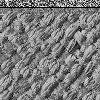
|
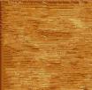
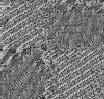
Original Weave Texture
|
Generated Weave, with static along top
|
2.3 Mixing Textures and Pictures - Basic Method
In mixing textures and pictures, we hoped to rearrange the texture in such
a way that it resembled the picture but still had the original pattern of
the texture.
We used a two step process to generate each pixel in the result image. First,
we found the window in the picture that matched our current window in
the result image. In figure 2, you
can see this is the upper left corner of the smile. Then, we searched through
the texture to find the k windows "closest" to our picture window in
terms of least mean squared error (with pixels in the window weighted by some
2D function - usually flat or gaussian). This ensures that that our pixel choice
will match the corresponding pixel in the picture to some degree.
The ANN VQ library natively supports searches for the k
closest neighbors to any given array. (In figure 2, I have highlighted a particularly
good match in the texture.) Next, we took the window we are generating from
the result image and compared it against all k matches to find the one with
the least error. This ensures that our final pixel choice will match
the surrounding texture as well.
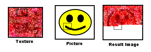
Figure 2
By changing the value of k, you can emphasize either the texture
or the picture. High values of k emphasize the texture by allowing a large
range of windows to be selected from the texture sample. Because many windows
are taken from the texture, they may not all resemble
the picture very closely - however, because there ARE many windows to choose from,
the result window will have an easier time finding a close match for the texture
generated so far. In contrast, a low value of k ensures that every window we choose in the texture
is very similar to the picture window. However, this means there are fewer choices when
matching the window from the result image to continue the texture.
This limits the texture-ness of the result image.
This trade-off between texture and picture is a general complication
in the problem rather than specific issue with our implementation. If I ask
you to fold a woman out of silk, you cannot fold a perfect woman (the silk
won't do that.) Thus, I can either have an image which looks a lot like silk
(but not especially like a woman), or I can allow you to do a few things not allowed
with real silk so that the woman shows up more clearly. By allowing such creative license with the
silk, I have lost some of its texture.
This becomes even more
evident when I try to model a sharp point with bubbles, or a curved line with
a rectangular lattice. Because this trade-off cannot be theoretically solved, we simply
take in the user's wishes as a parameter and produce an image somewhere between
the texture and the picture.
2.4 Problems with the Basic Method and the Solution: the Overlap
Method
Although the basic method produced good results, we noticed a few problems
and attempted to solve them with an alternative algorithm that seemed more
theoretically correct. The major problems with the first method were its deterministic
behavior, the determination of absolute error bounds, and ignoring relative texture error.
The overlap method addresses
these concerns, but it also runs signficantly slower. (See the
further explorations section for ideas we have for speeding this up. We think it would
be very possible to make this run at least 4 times faster, but did not have
time to test all our ideas.)
2.4.1 The first problem with the Basic Method: Not Random Enough
First, the basic algorithm always picks the best match from the k choices generated
by the picture. This can lead to overly deterministic behavior that creates
"garbage" areas in the result image. If the algorithm starts generating
a whole lot of pixels in a row that look the same, this can "lock"
the generator into a bad cycle where it always picks the same window as long
as it is available. We see this problem in the picture of the woman below:
Woman: generated with k = 2000
and basic method.
As we can see, the eyes came out well. However the bottom half of the picture
shows two repeated folds. This is caused by the deterministic behavior of
the basic algorithm. The overlap algorithm solves this problem by always locating
at least 10 usable windows and than picking randomly from this base. (Of course,
you could change this 10 to 15, 100, or 5000 if you wanted something more
random.)
2.4.2 The second problem with the Basic Method: Error Bounds
The second problem with the basic algorithm came in the setting the value of
k. k is specified as an absolute number of window choices instead of as an error-bound
from the ideal window. Ideally, we would want k to change depending on the
error rate. For instance, suppose we wanted to generate a picture from this
coin texture:

There are a large number of silver coins and a few scattered gold coins. When
generating a dark region of the picture, I would want to see only gold coins, of
which there are few (so k must be small to limit the number of windows returned).
However, when working with a light region of the photo,
I would want to see as many silver coins as possible so that texture could
easily find a match. (k must be large) In order to accomplish this, I have
to let k change depending on the window I am matching. Ideally, we would
like to set an error bound and allow all matches less than that bound (as the
original plain texture synthesis algorithm does). However, there is some difficulty
then in making sure that there are enough windows to choose from, so this is
perhaps an area of further research.
2.4.3 The third problem with the Basic Method: Ignoring Texture
Error
In addition to setting an error bound on the quality of the matches to the
picture, it is important to look at the quality of the texture we are generating.
For instance, suppose I set an error bound of 1.5 on the photo, and it turns
out that there are no decent matches to the texture in that region. However,
if I was willing to loosen the error bound on matching the photo just slightly,
I would get a huge payoff in terms of matching the texture. In this case,
we want to trade off the error on the photo with the error on the texture.
In other words, we should take into account the texture error when setting
the error bound for the picture at every step.
2.4.4 The Overlap Algorithm's Solution
For each pixel generated, the overlap algorithm takes every window in the sample
texture and rates them on two scales. First, it creates two arrays - one array ranking
the windows on how closely they match the picture window at that point, and another
ranking the windows based on how closely they match the texture generated so far in
the result image. Next, the algorithm finds the 10 windows which are present in
both arrays (i.e. which "overlap") and have combined minimum error.
(Note, this is not as inefficient as it may at first appear because
we don't actually need every window and this ranking is native to the ANN
VQ library. Also, we almost always stop before we have traversed the entire ranking.)
To figure out what the "combined minimum error" is, we first need a notion
of the error of each element within an array. To find this we compute the
weighted mean squared distance of every window in the array from
the respective picture or result image windows. However, we need to normalize this
metric between the two arrays - we don't want the texture generation process to
be biased toward either the picture or (more likely) the texture, simply because
their windows bear a much closer resemblance to the sample texture. To normalize an array,
we simply divide each distance in the array by the first element (the MINIMUM distance).
In other words, the new metric for error measures
much worse you are than the best possible match in your array (i.e. twice as bad, four times as
bad, etc.)
Now we can calculate the combined error of a window present in both arrays.
A simple solution
would be to define the combined error as the sum of the error from each array. We decided
to give our program more flexibility by taking in a weight parameter, w, and
using the weighted sum of the errors of the two arrays to compute the combined
error in choosing a given window from the sample texture. Thus, by increasing
or decreasing w, you can emphasize either the texture or the image to a greater
or lesser extent. Values for w less
than one emphasize the texture and values greater than 1 emphasize the image.
As you can see, we have solved the randomness problem by taking 10 answers
at every point instead of just 1. Additionally, we have thrown out the absolute
k value in exchange for a method that tries to find a compromise between the
texture and picture with an emphasis on the error at each point. Unfortunately,
this theoretically superior algorithm comes with a significant cost tradeoff.
Whereas the basic algorithm can run in 5 to 30 minutes, the overlap method
usually takes upward of an hour, and possibly several hours. For this sort
of slow down, the results it generates generally aren't worth the trouble.
3.0 Results
In studying the algorithms, we looked a number of factors including the relative
merits of the basic and overlap algorithms (section 3.1), the tradeoff between
emphasizing the texture and picture (section 3.2), the types of textures that
can be applied easily to pictures (section 3.3), and the time needed (section
3.4).
3.1 Basic vs. Overlap Methods
Unfortunately, because these two algorithms are fundamentally different and
take in different parameters (k vs. w) it is very difficult to find corresponding
parameters and compare the algorithms' performance.
However, we are able to highlight the essential difference with
the coin image. As we mentioned earlier, the coin image presents a problem
for the basic algorithm because so much of the picture is silver coins. If
we don't constrict the k very tightly, it will cover almost the entire image
in silver coins. On the other hand, if we constrict k tightly enough to force
it to use gold coins on the dark areas, it will not have enough leeway to
produce any sort of texture at all. We can see this tradeoff in the images
below:
|
|
|
|
|
|
Original Texture
|
High k value (note, you cannot see the smiley
face at all.)
|
Low k value (note, there is almost no texture
at all in the silver background)
|
Original Picture
|
The overlap algorithm attempts to solve this problem by using error bounds.
This should allow it access to a greater portion of the silver coins while
still using gold coins for the dark areas. The coins are a difficult
picture to generate for reasons discussed below, but we still see
better results with overlap:
Notice that the tradeoff is no longer a choice of getting a face or not getting
a face, instead, by emphasizing one aspect over the other we trade off the
continuity of the coin image with the correctness of the facial image. However,
both options take into account the coins as well as the picture. For instance,
it would be impossible to get the third image with the basic algorithm.
Overall, as the example above demonstrates, the overlap algorithm offers more
precise fine tuning. However, it takes much longer and most simple texture/picture
combinations
appeared just fine with either algorithm.
3.2 The compromise between texture and picture
Another issue we explored was the compromise between the texture and the picture.
As the following results demonstrate, changing the trade-off value leads to
significantly different images. Too much emphasis on the texture tends
to produce results similar to the texture with the underlying image barely visible, while
too much emphasis on the image creates a version of the image with the color scheme
of the texture and only the basic "feel" of the texture visible.
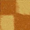
Here, we have moved from the original wood image to a checker pattern. Note
that the wood looks a little funny partly because the original texture doesn't
exactly look like wood. Nevertheless, even in the results most skewed towards checkers,
we can see the basic wood grain texture.
|
|
|
|
|
|
|
|
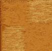
Original Wood
|
Wood Emphasis (w = 0.5)
|
Slight Wood Emphasis (w = 0.75)
|
Even emphasis (w = 1.0)
|
Checker emphasis (w = 1.25)
|
Original Checker Picture
|
These same images appeared above, but we wanted to look at them again in light
of the tradeoff between textures and images. Notice that the plain image generation
captures the coins pretty well. As we move toward the picture, we see the
round edges of the coins disappearing, but it nonetheless maintains a very
metallic texture.
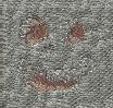
Here, we are again making the woman (but this time out of bricks). As we move
toward the image, the bricks lose their rough quality, but we maintain the
horrizontal stripes and divisions that represent the brick wall.
|
|
|
|
|
|
Original Stone Texture
|
Notice how the stones capture the rocky look from
the texture
|
Here, the stones look slightly smoother, but we
can see her mouth (and nose?)
|
Original Picture
|
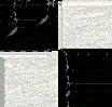
Here, we have emphasized either a weave pattern or a checker pattern. Note
that the weave begins to gradually disappear as we pay more attention to the
checkers.
|
|
|
|
|
|
|
|
Standard generation
|
emphasis on weave (k = 700)
|
emphasis on checkers (k = 400)
|
|
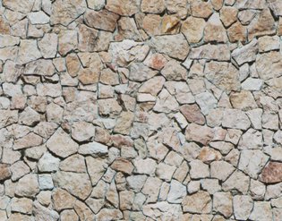
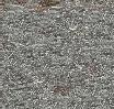
3.3 Results with different kinds of textures
We ran the algorithm with a number of different kinds of textures and found
two basic characteristics that affected performance. First, textures work
much better when they are comprised of small units. This is because our algorithm
effectively cuts the texture down to about 1/10 the size before generating
more of it. (By the time it takes only the pieces that look like the picture,
there is not nearly as much material to work with.) So, if the texture was
comprised of only 20 large stones, we now have only 2 or 3. Obviously, generating
texture from only two or three samples is difficult. Thus, the program performed
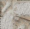
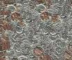
better on textures with many small or tiny units such as the stone wall at
the beginning of the paper or the texture in marble.
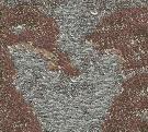
Second, the texture must match the picture to some extent in order to combine
the two effectively. For instance, if the texture consists of many high contrast
pebbles, and the image is a gently rolling landscape, it will be unable to
render the image well with the texture. We can see this problem below with
the pebbles and the checkers. We can effectively map the stone like quality
onto the checkers, but because they are a constant color, they provide no
place for the pebbles to end and start a new pebble. Thus, each square of
our texture becomes one large pebble. (However, when we do provide an opportunity
for a contrast change from white to black, we see a strong pebble-like edge
as it curves down to the border instead of stopping abruptly.)
| |
 This
is the original texture that we forced all the other textures to resemble. This
is the original texture that we forced all the other textures to resemble. |
 |
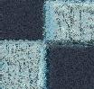
 Notice
the marble texture in the squares. In particular, the white squares
have the ridges from the marbles and, the borders between white and
black appear raised with shadows and highlights. Notice
the marble texture in the squares. In particular, the white squares
have the ridges from the marbles and, the borders between white and
black appear raised with shadows and highlights. |
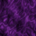 |
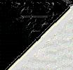
 Here,
the "ether" pattern has molded itself to the square shape.
However, we don't see harsh lines dividing the regions. Instead, the
purple haze gently swirls from dark to light. Here,
the "ether" pattern has molded itself to the square shape.
However, we don't see harsh lines dividing the regions. Instead, the
purple haze gently swirls from dark to light. |
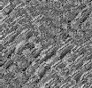
 |
 Here,
the upper-left and lower-right squares captured the distinct weave
pattern, while the other two show a subdued version of the same pattern. Here,
the upper-left and lower-right squares captured the distinct weave
pattern, while the other two show a subdued version of the same pattern.
|
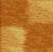
 |
 Beause
the wood patterns were too large for the window to capture, this image
only caught the wood texture, and not the lines in the wood. Beause
the wood patterns were too large for the window to capture, this image
only caught the wood texture, and not the lines in the wood. |
 |
 Similar
to the one above, these rocks were too large for the window to capture
the whole rock. Nonetheless, we have created a checkerboard with a
distinctly rock-like appearance. We just have one large rock with
a checker pattern instead of 100 small ones. Similar
to the one above, these rocks were too large for the window to capture
the whole rock. Nonetheless, we have created a checkerboard with a
distinctly rock-like appearance. We just have one large rock with
a checker pattern instead of 100 small ones. |
 |
 Once
again, the pebbles are too large for the texture to capture individual
"pebble" units. However, it does have a rock-like-feel,
and the edges between checkers have the lights and shadows the rocks
have. In other words, the image came out as four large square shaped
rocks. (They have rock like edges and textures, but they are too large
to resemble pebbles.) Once
again, the pebbles are too large for the texture to capture individual
"pebble" units. However, it does have a rock-like-feel,
and the edges between checkers have the lights and shadows the rocks
have. In other words, the image came out as four large square shaped
rocks. (They have rock like edges and textures, but they are too large
to resemble pebbles.) |
In the first example above, we mapped a checker shaped marble pattern onto
larger checkers. This may at first appear too easy. We just wanted to assure
you that the difficulty (or ease) of this task had nothing to do with them
both being checker shaped or black and white. Because the algorithm works
on the pixel level, it can map onto any shape or color. Below, we have mapped
the same marble checkers onto a purple and green triangular pattern successfully.
|
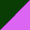 |
 Here,
we modeled a purple and green triangle pattern with the square shaped
marble check. (Note, it did have a little bit of trouble on the edge
because there is no place in the texture with a diagonal edge. But,
if you squint it looks fine. :) Here,
we modeled a purple and green triangle pattern with the square shaped
marble check. (Note, it did have a little bit of trouble on the edge
because there is no place in the texture with a diagonal edge. But,
if you squint it looks fine. :) |
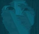
After tuning the algorithm map textures onto the square pattern, we decided
to try a more difficult challenge and map textures onto a human face. The
subtle shading and compexity can make this a much more difficult task. Nonetheless,
we believe the algorithm captures her face in various textures. (We also tried
a big smiley face, but those images just looked silly - who wants a brick
wall to smile at them?)
| |
This
is the picture that we modeled with various textures below |
|
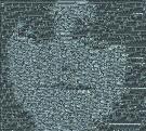 Here,
the brick wall has been rearranged to create the woman's face. The
bricks are small enough that the window could capture them and we
actually see individual bricks in our result image. Here,
the brick wall has been rearranged to create the woman's face. The
bricks are small enough that the window could capture them and we
actually see individual bricks in our result image. |
|
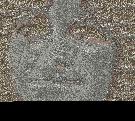 This
time, the coins were too large for the program to represent the full
coin and still emphasize the woman's face. Thus, we only have small
pieces of coins in her face and hair. This gives her a distinctly
metallic shine. In other words, we have the right material, but not
in entire units. This
time, the coins were too large for the program to represent the full
coin and still emphasize the woman's face. Thus, we only have small
pieces of coins in her face and hair. This gives her a distinctly
metallic shine. In other words, we have the right material, but not
in entire units. |
|
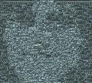
 Notice how she is soft in this picture unlike the other ones where
she appears either stoney or metallic. This is an indication that
we have captured part of the silk texture. Unfortunatly, in the trade-off
to also see the woman, we do not have the extended folds apparent
in the original image.
Notice how she is soft in this picture unlike the other ones where
she appears either stoney or metallic. This is an indication that
we have captured part of the silk texture. Unfortunatly, in the trade-off
to also see the woman, we do not have the extended folds apparent
in the original image. |
3.5 Timing
We ran timing data for all our results, but they don't mean much because the
times depend on the size of the sample texture, the generator image, the value
of k (or w), the error rate we allow, the texture we are generating, the number
of overlaps we look for, etc. A more thorough analysis of timing data may be warranted
when a more finalized algorithm is developed in the future, but for now we felt it would be
better to simply get a feel for the approximate time each algorithm takes:
| Algorithm |
User Time |
| Efros and Leung Texture Generation |
hours |
| Texture Generation with VQ (best pixel first) |
30 minutes |
| Texture Generation with VQ (raster-scan order) |
Seconds / Minutes |
| Basic Texture / Picture Combo Algorithm |
5 to 30 minutes |
| Overlap Texture / Picture Combo Algorithm |
1 hour to many hours |
Overall, these algorithms took a long time, but with the speedup VQ provides it is
still reasonable. Also, additional ways of speeding up the algorithm exist, some of which
we discuss below.
4.0 Further Explorations
While we think our results are pretty cool, there are a number of ways they
could probably be improved and/or speeded up. Here are a few of our ideas:
First, we would like to speed up our basic and overlap code even further by
using some of Wei and Levoy's other ideas. They had a number of ways to make
texture generation go faster and we only had enough time to implement one
of those (namely VQ, which provides the biggest speed gain).
Second, we'd like to try the algorithm using different resolutions for different
matches. At a simple level, we could follow Wei and Levoy's suggestion of
creating a pyramidal structure so that we can try larger windows in less time,
by comparing the larger windows at a lower resolution. In addition to the speed gain,
we think it
would also be interesting to apply this to our specific problem by matching
the picture at one resolution and the texture at another. This might give us more
of an ability to match large-scale structure in one image (the picture) and small-scale
structure in another (the texture).
Third, we thought that we could get by far the biggest speed up by changing the way we found
overlap points. As shown in the diagram below, we currently search the vector space out from each of
the two original points looking for the overlapping regions. (The areas where the green and red
circles cross). If we could instead average our original points to find the point half-way in between,
and than do a search out from that point, the whole process would take seconds instead of hours.
However, there are a couple of hurdles before implementing this. First, we would have to define what
the half-way in between point was. This would probably be computed by first finding the closest points
(in our space) to each of the two endpoints and than taking some sort of weighted average. Even after
we determine this point, the results we get will be slightly different from taking points closest to
the two endpoints. As shown below, the shape of the blue circles is different from the shape of the
overlap between the red and green circles.
Fourth, if we could get the algorithm to move quickly enough, it might be interesting
to try animating images made out of textures. Of course, if we randomly generated
an image for each frame, we would simply see static when they move quickly
across each other. Thus, we would probably want to match a potential picture
against 3 things: the photo, the generated texture, and the previous frame
of the animation. If we could get this to work, it could be REALLY cool. Faces
moving in sand?
Fifth, as you can see in the image of the woman's face, the limited color
scheme of the texture can provide problems. If someone has many shades to
their face, but all of them are lighter than the lightest shade of the image,
nothing will show up. To solve this problem, it would be neat to have the
algorithm automatically adjust the darkness and lightness of the photo or
picture to make it fall into the color range of the texture.
Sixth, we noticed that the overlap function usually stopped computing after
going through only a small fraction of the arrays. Unfortunatly, which array
stopped first depended greatly on the image and on the value of w. We could
save a significant amount of time by stopping it early ourselves after observing
a few rounds to see where it happened to stop. In other words, if we could
create an adaptive algorithm that computed values for the lengths of the arrays
and the picture was generated, we could save a significant amount of time without
a large loss of quality.
Finally, we think this project was the first step toward combining textures.
With a simple modification to our algorithm, you could allow both the texture
and the "picture" to generate texture synthesis style and than use
the same mechanism to create one texture out of the other. This would allow
you to generate combined textures of any size and shape.
Feel free to email us with questions/comments: Alex
Eilhauer (eilhauer@fas.harvard.edu), Alice
Pritikin (pritikin@fas.harvard.edu), or Dylan Weed
(dweed@fas.harvard.edu)


